Pinch Analysis Guide
Welcome to your Pinch Analysis guide! After completing the example problem provided below, you are encouraged to explore different plots and cost functions!
Problem Statement
ΔTmin = 20°C
| Stream | Mass Flowrate (kg/s) | Specific Heat Capacity (kJ/kg K) | Heat Capacity flowrate, CP (kW/K) | Initial (Supply) temperature (C) | Final (Target) temperature (C) | Heat Load (kW) |
|---|---|---|---|---|---|---|
| Cold | 0.25 | 4 | 1.0 | 20 | 200 | +180 |
| Hot | 0.4 | 4.5 | 1.8 | 150 | 50 | -180 |
Flowsheet
Note: The Heat Integration (HI) Case operation is a tool used to design heat exchanger network (HEN) and perform simulation analysis on the HEN. HI Case contains one scenario/one set of input parameters and one design/one Grid Diagram that displays one HEN.
The Heat Integration (HI) Project operation is used to design a heat exchanger network (HEN). The HI Project is similar to the HI Case operation but the Project can contain multiple scenarios and designs.
Step-by-Step Guide
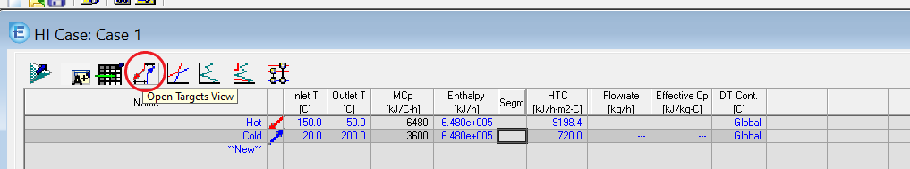
1. Open HI Case

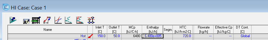
2. Add Hot Stream Data
Enter the inlet temperature, outlet temperature, and enthalpy.
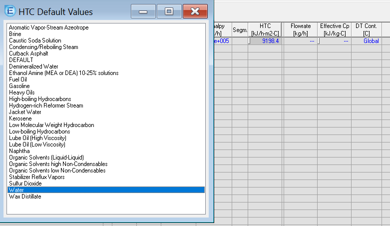
3. Configure Heat Transfer Coefficient
Double click on HTC row and choose heat transfer fluid from the database.
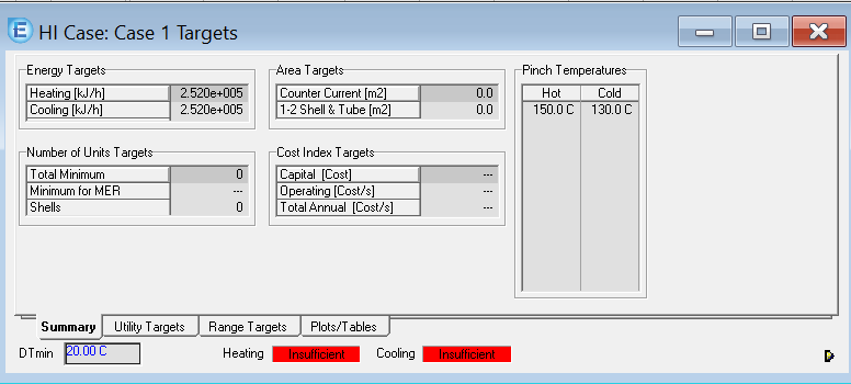
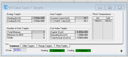
4. Set Pinch Temperature
Open Target View to add pinch temperature.
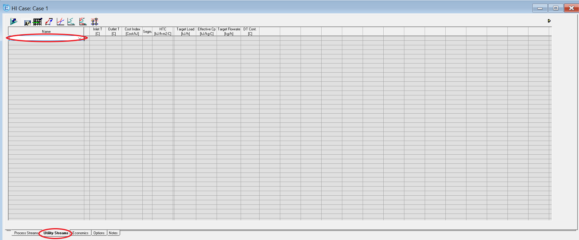
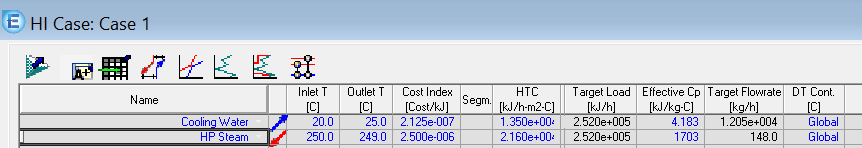
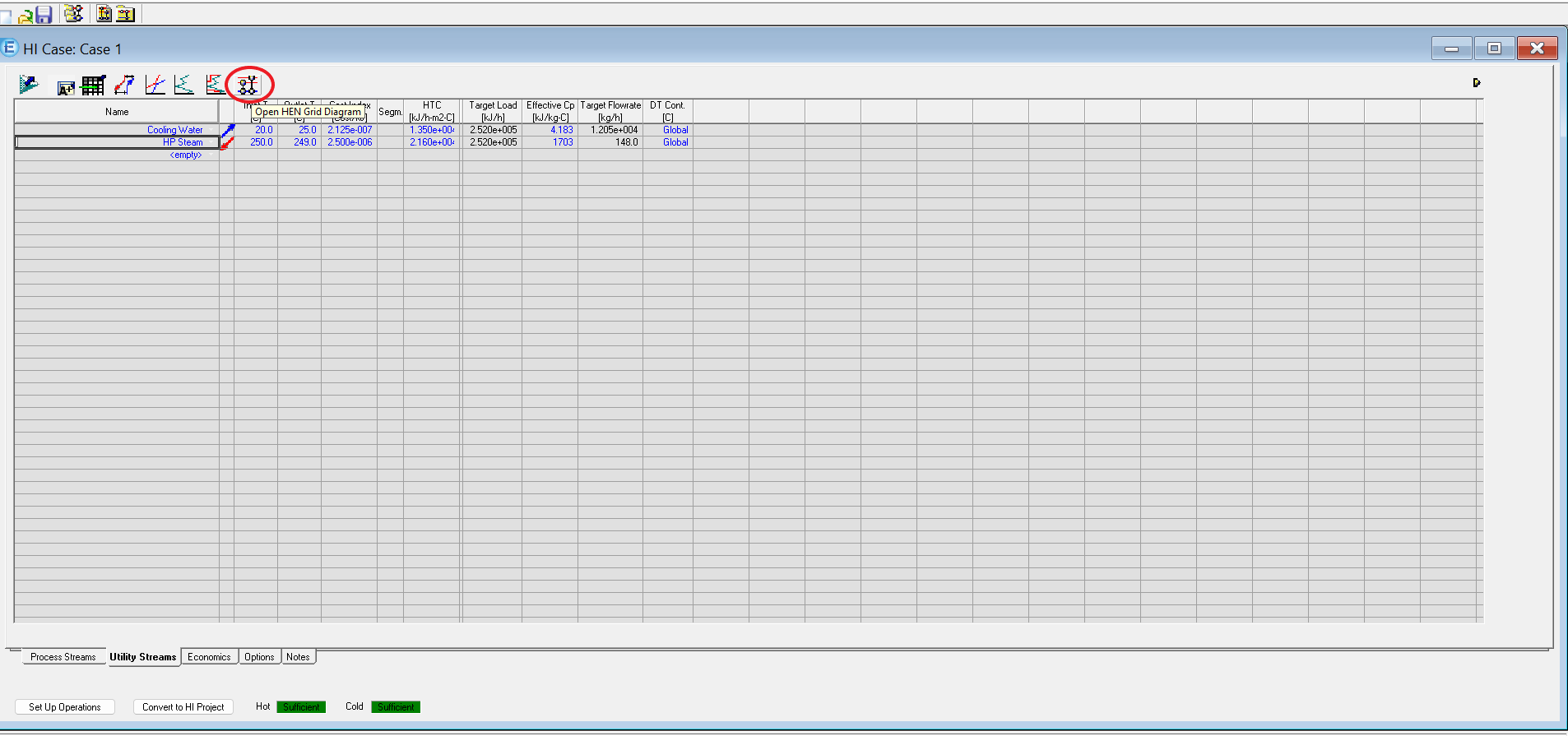
5. Define Utilities
Open Utility Streams and configure the utilities.
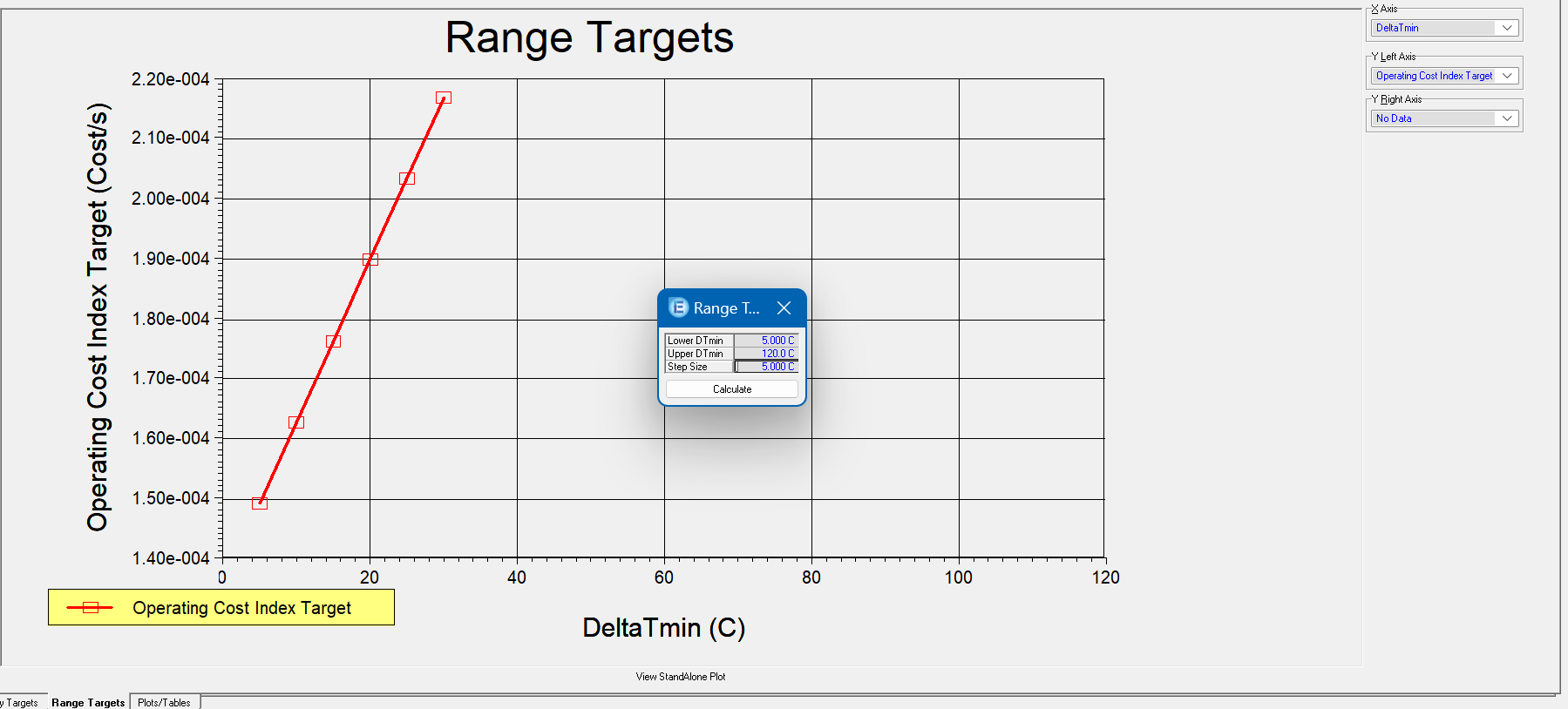
6. Create Range Targets
Open Targets View, go to Range Targets, and create different plots by defining ranges.
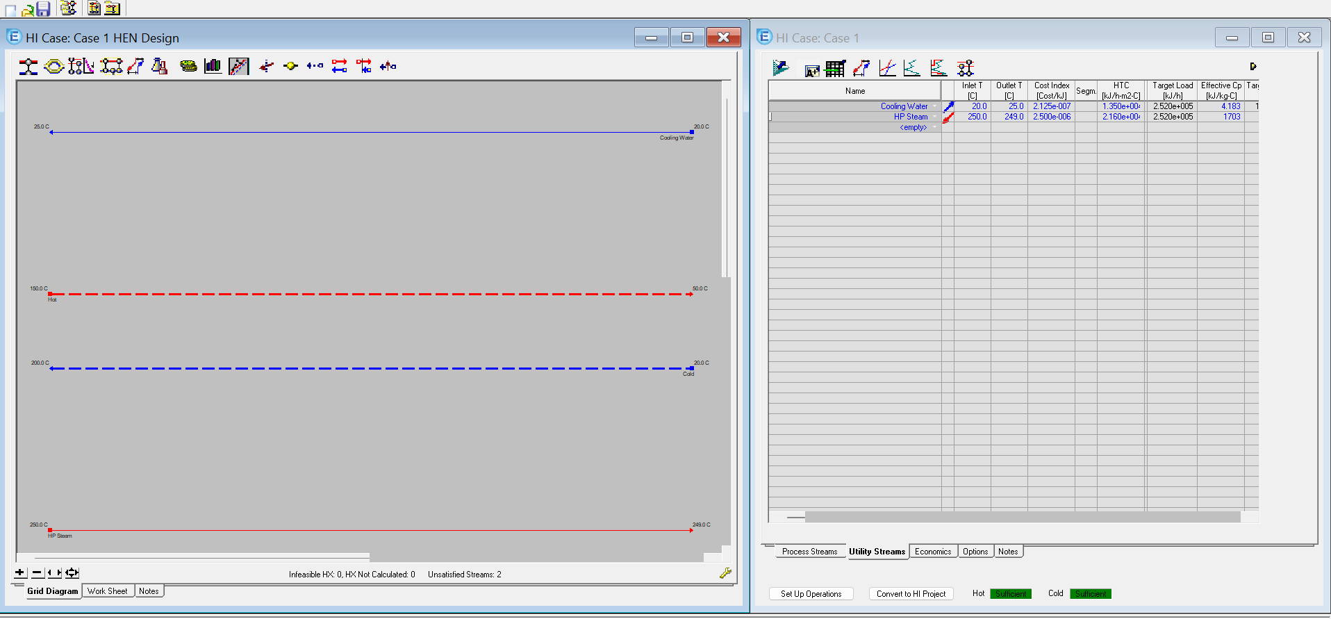
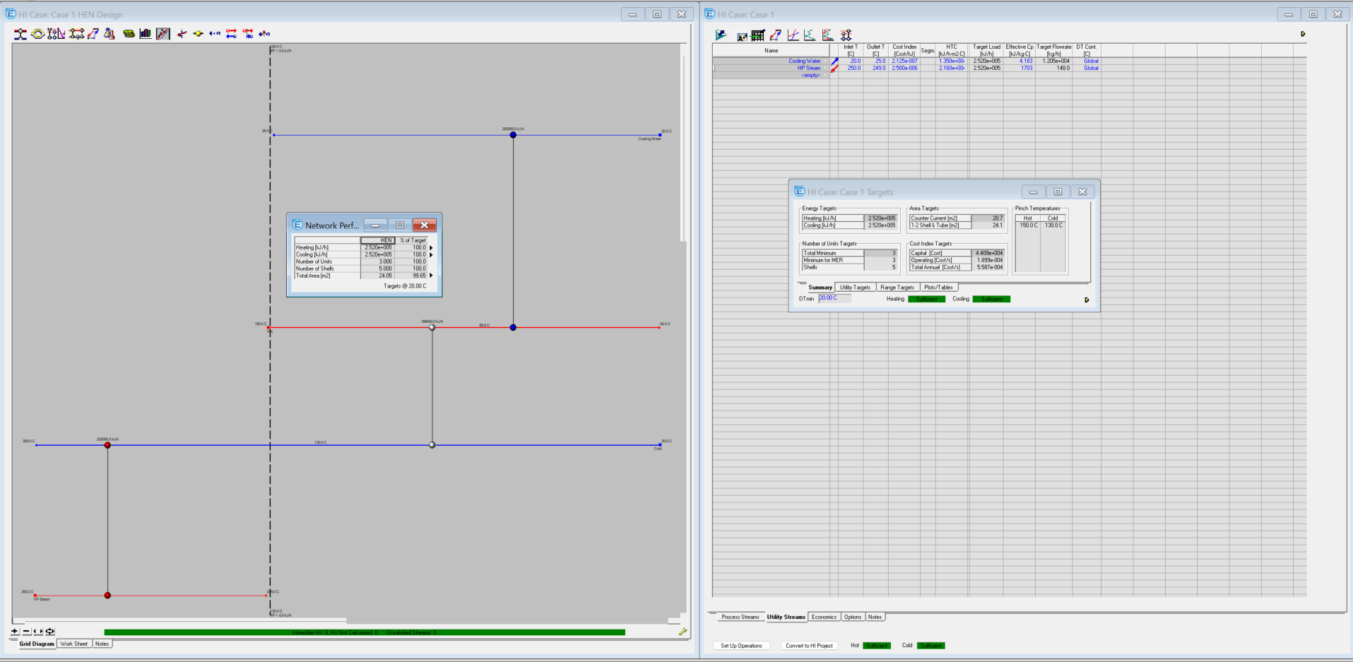
7. Open HEN Diagram
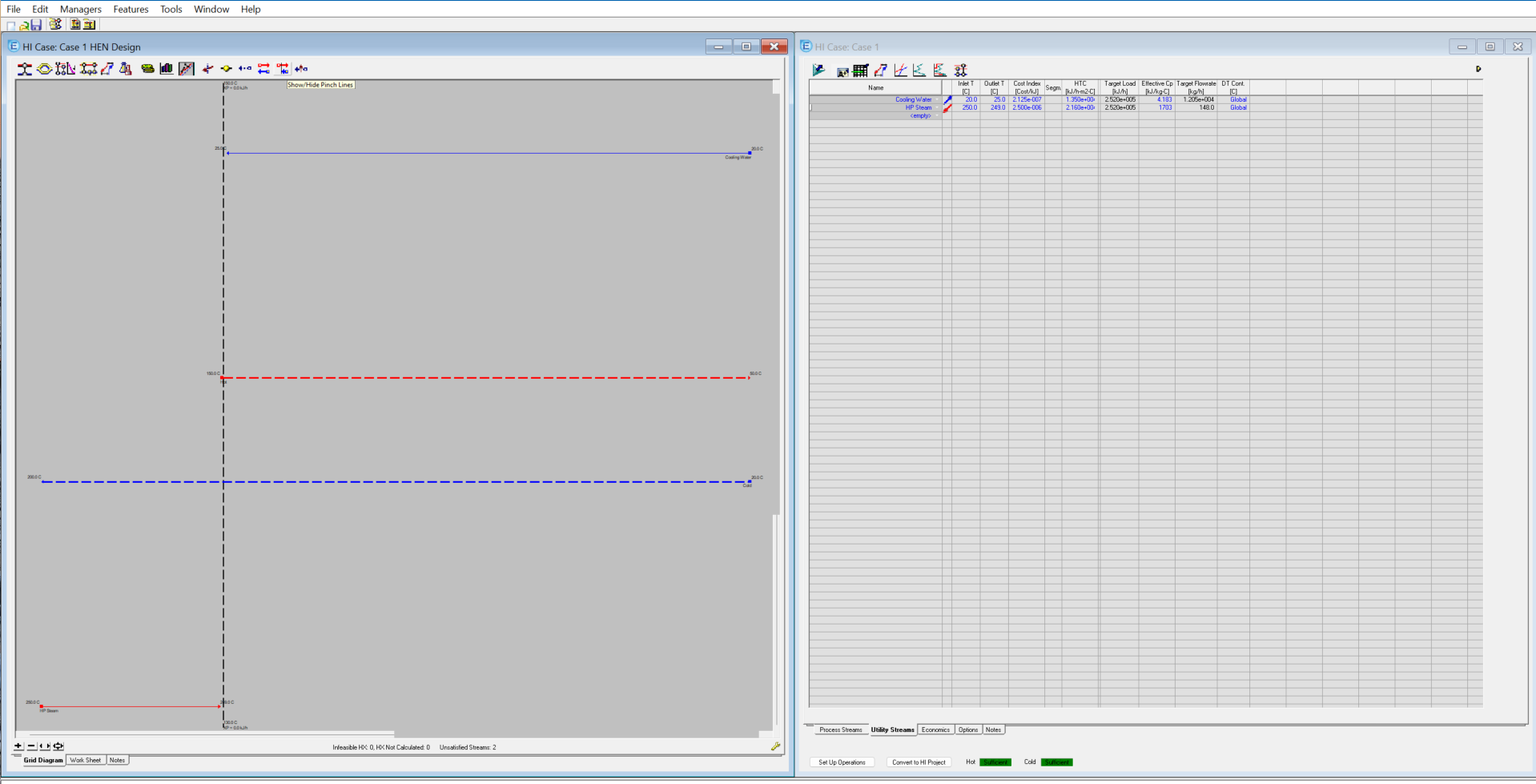
8. View Pinch Lines
Click "Show Pinch Lines" to see above and below pinch regions.
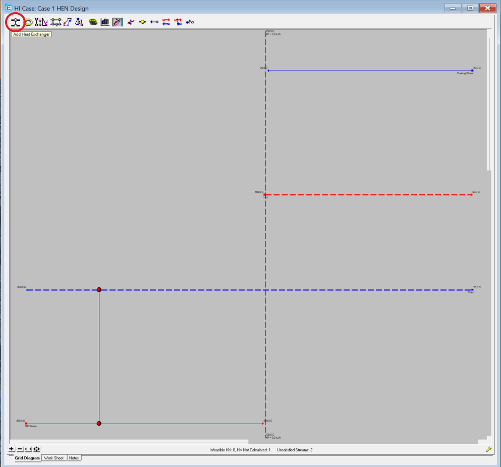
9. Add Heat Exchangers
Right-click to add heat exchangers and drag them to connect streams.
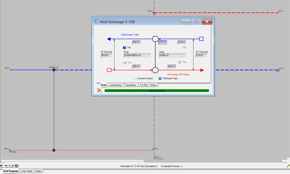
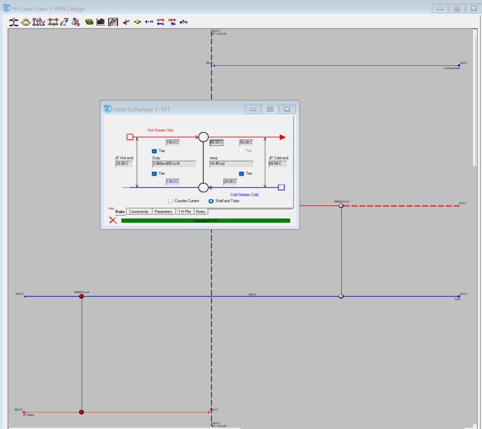
10. Configure Heat Exchangers
Double-click each heat exchanger to configure its parameters.
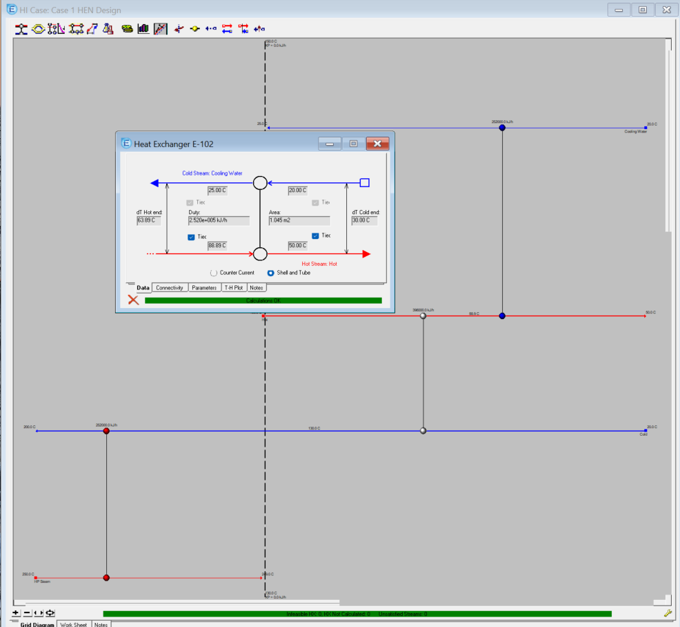
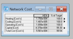
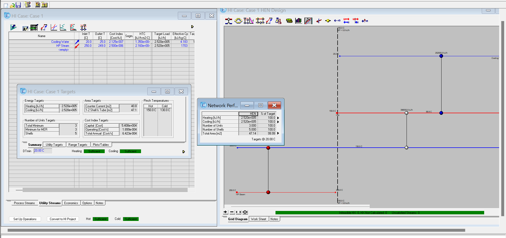
11. Review Performance
Compare your results using the Targets and Performance views.
Results
Initial calculations from Heat Integration Case:
Your optimized design results: