Process Simulation Guide: Refrigeration Loop
Welcome to your first Aspen HYSYS guide!
In this guide, we'll walk through building a simulation of a refrigeration loop.
Problem Statement
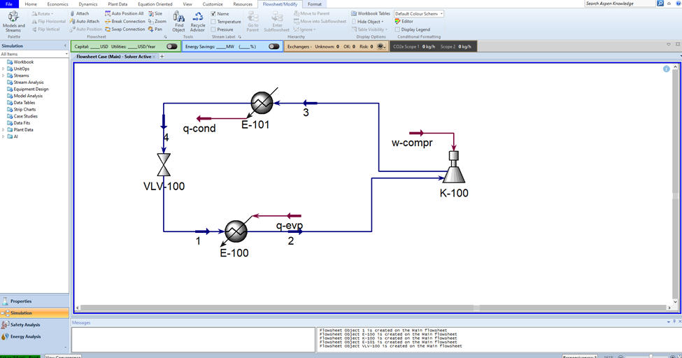
125 kmol/hr propane is fed to an evaporator where it absorbs heat from a high performance computing room at a rate of 1.5e+6 kJ/hr. The exiting propane stream from the evaporator is adiabatically compressed with 70% efficiency and then fed to the condenser to eject heat from the system. Propane leaves the condenser as a saturated liquid at 45 degrees C and undergoes valve expansion to 302 kPa. The low pressure propane is fed back to the evaporator, completing the refrigeration cycle.
The evaporator and condenser pressure drops are 5 kPa and 30 kPa, respectively.
Step-by-Step Guide
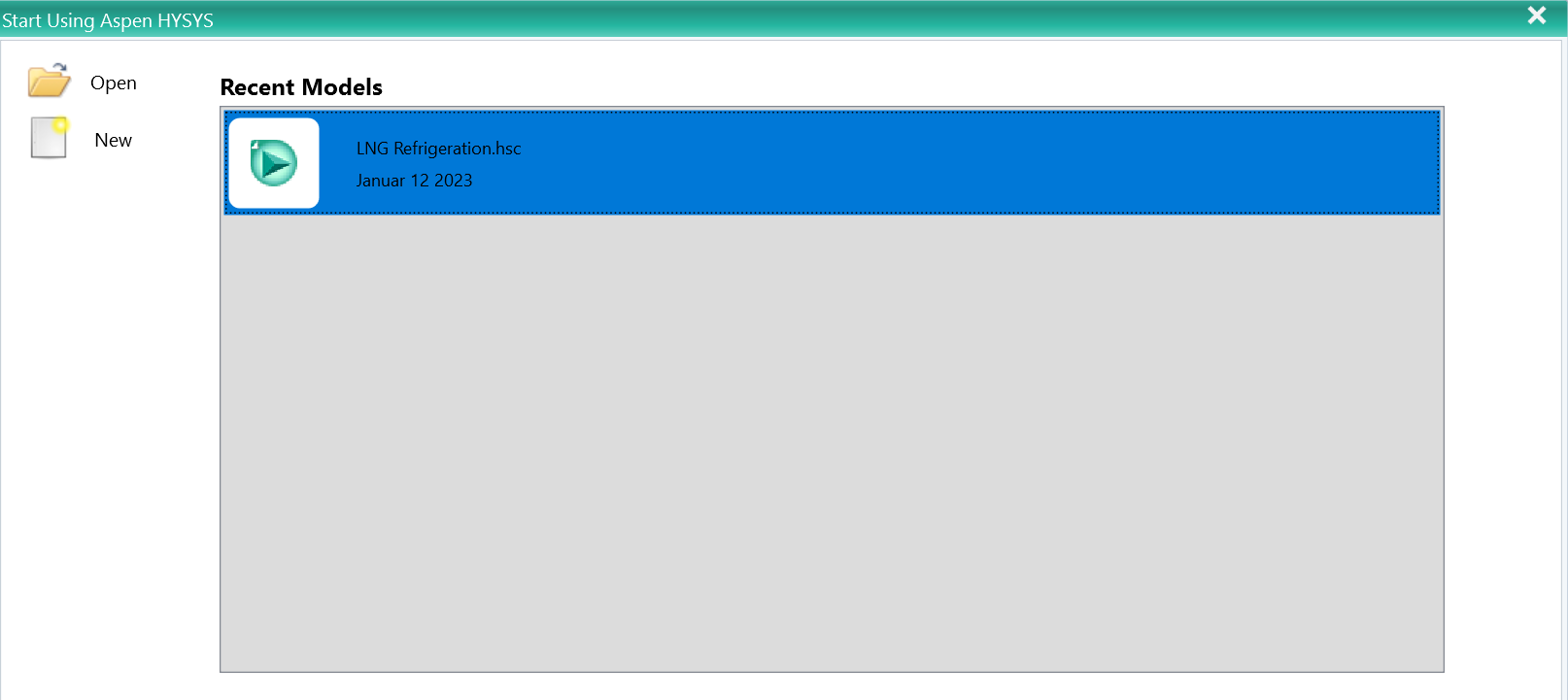
1. Open a new project
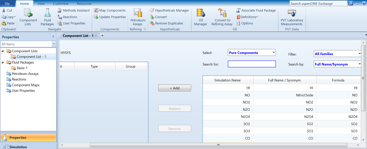
2. Add propane as the component to the system
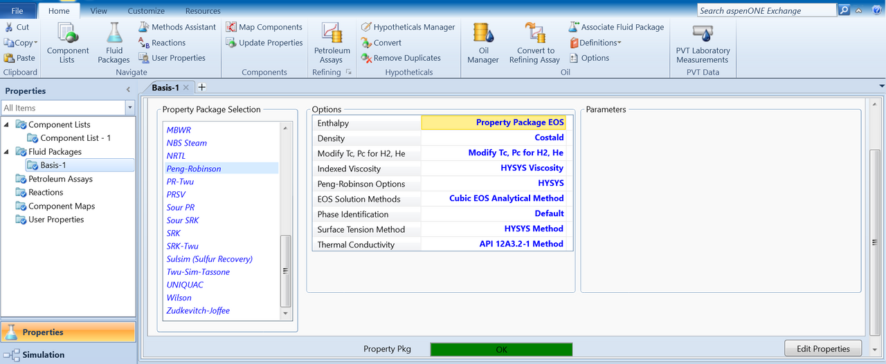
3. Choose the Peng-Robinson equation of state as the fluid package
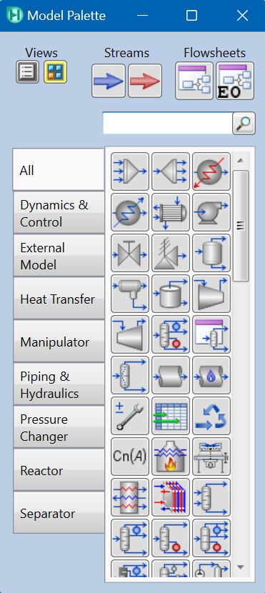
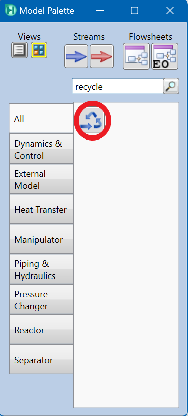
4. Set up the Model Palette
Back on the home screen, locate the Model Palette under Flowsheet/Modify. Then open the Model and Streams palette as shown below.

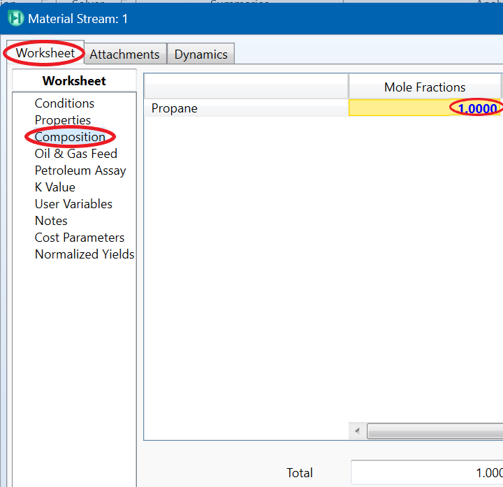
5. Configure stream compositions
Make sure that after adding your first stream, you have defined the Composition. Since propane is the only component in your process, the propane mole fraction is one.
6. Add the Recycle Block
Depending on different process simulations, you may need to add the Recycle Block to your flowsheet. This installs a theoretical block in the process stream to solve recycle loops, hence allowing the simulation to converge.
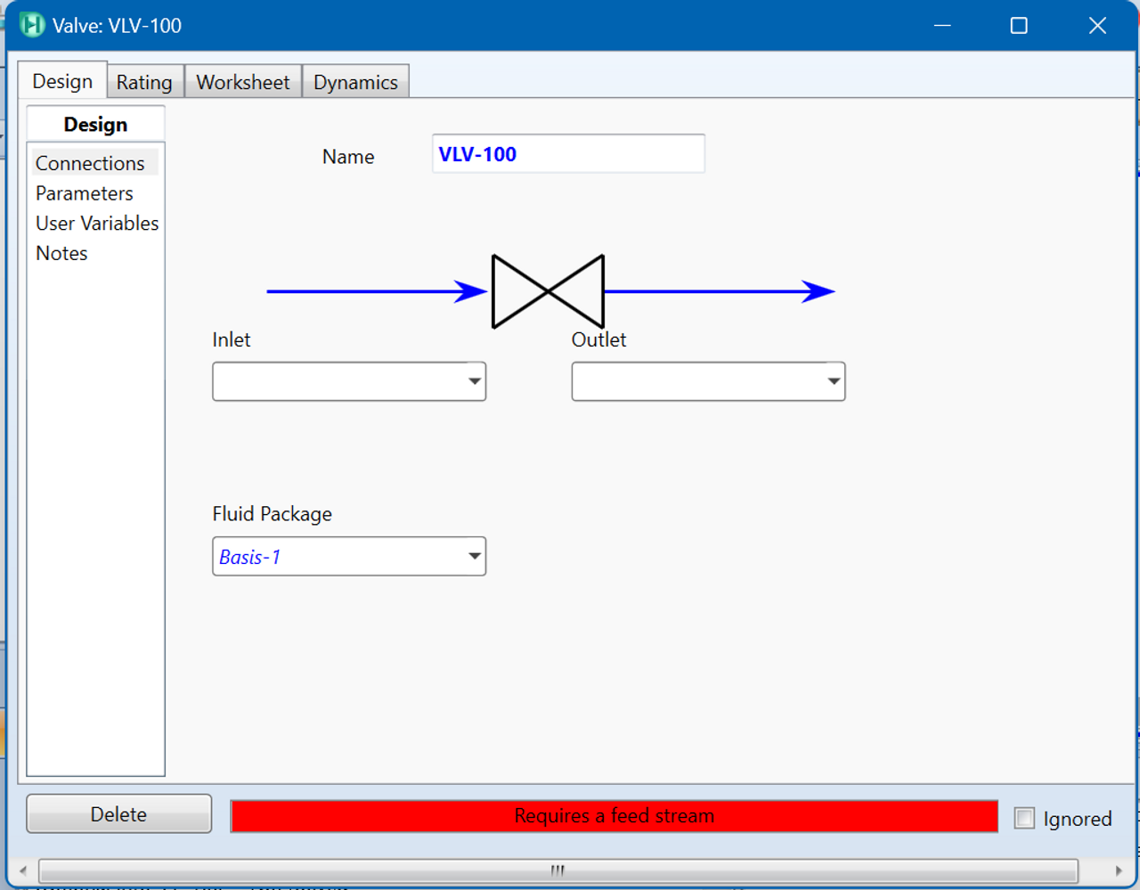
7. Configure equipment and connections
Once you have added the necessary four pieces of equipment into the flowsheet, double-click each piece of equipment for more details and specifications. You will need to modify the settings to input all of the given information from the problem statement and connect the pieces together in the proper order.
For example, double-click VLV-100, to rename the inlet/outlet streams. The streams can also be re-assigned to adjacent pieces of equipment to make the appropriate connections.
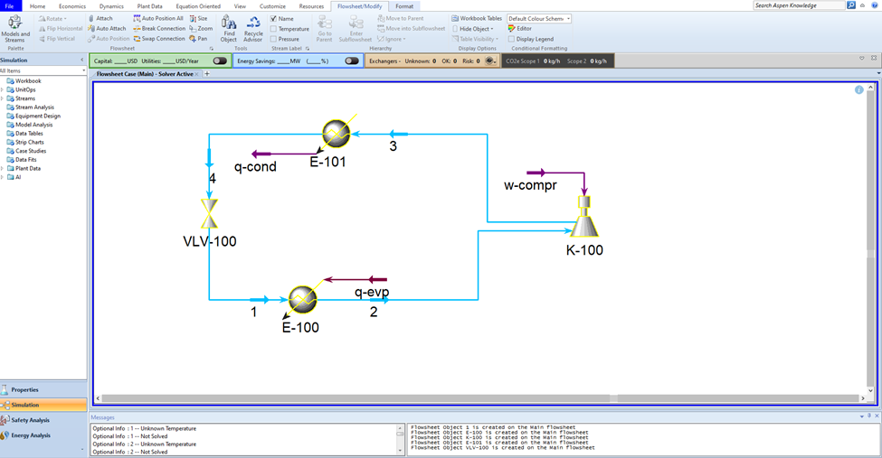
8. Review the flowsheet
Your updated flowsheet may slightly vary in appearance to the example below, but should include the same streams, equipment and sequence of steps. The button "Auto Position All" can be used to adjust the layout:
9. Run the simulation
If you double-click each piece of equipment, you should see the green "OK" indicator. Click Active on the home screen to run the simulation. Confirmation that the system is running is indicated by the color change to dark blue streams and equipment outlines.
Solution
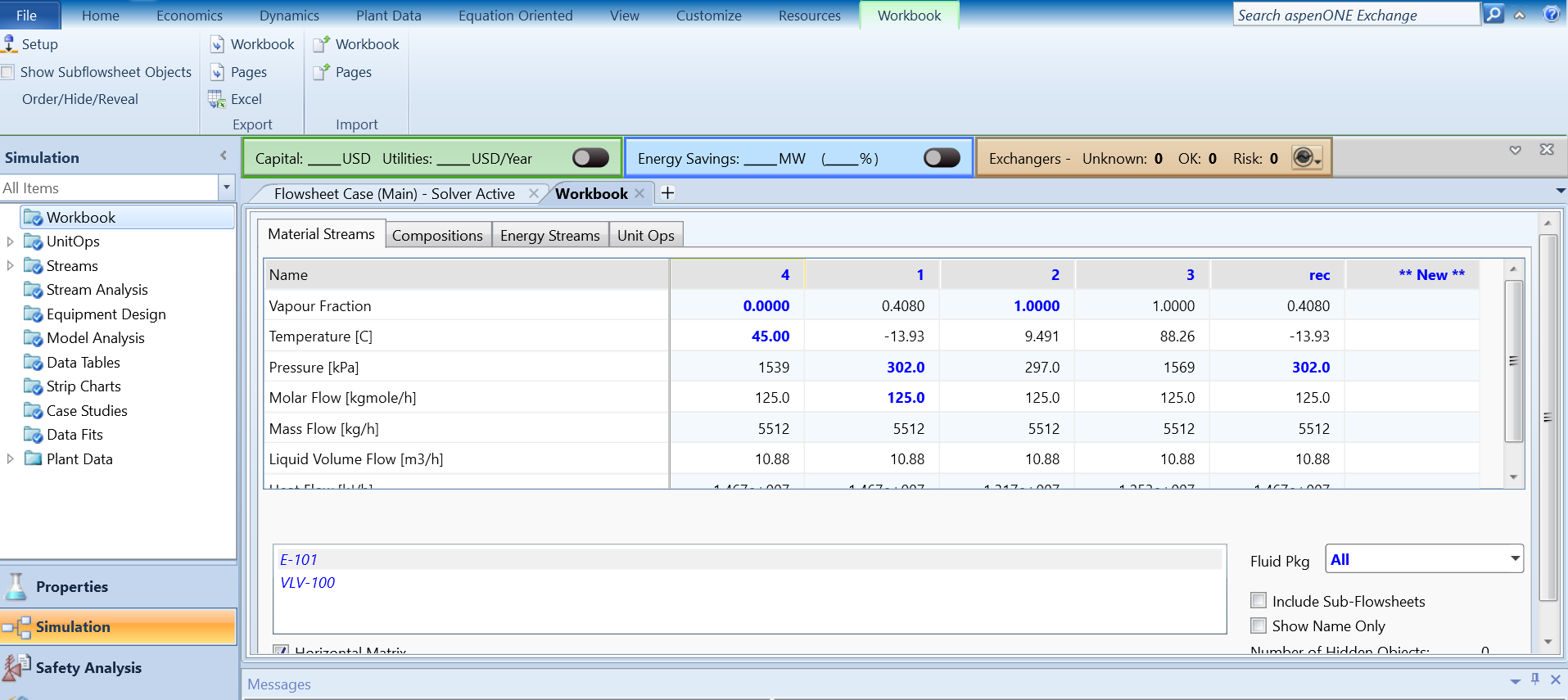
To see all your flowsheet streams together click Workbook from the ribbon.

Material streams specifications:
Questions for Understanding
- What is happening in the system? Can you walk through and explain the four steps of a refrigeration loop?
- Can you define a specific utility for condenser or evaporator? Try and find out.
- Why is Peng-Robinson an appropriate equation of state for propane?